The Micromouse robot is built to solve mazes autonomously. The challenge here is to navigate from a starting point to the end of a maze, learning the path and optimizing it.
Key Components:
- Microcontroller: Arduino, ESP32, or any other suitable microcontroller.
- Sensors: Ultrasonic or infrared sensors for detecting walls.
- Motors and Wheels: A set of DC motors with encoders for precise movement.
- Power Source: LiPo battery (lightweight) to ensure enough power for all sensors and motors.
- Algorithm: Flood fill, left-hand or right-hand rule for solving the maze.
How It Works: The robot uses its sensors to detect walls and open spaces as it explores the maze. The chosen algorithm helps it navigate and, once it finds the end, it remembers the path and optimizes it.
Key Tips
Mechanical Design
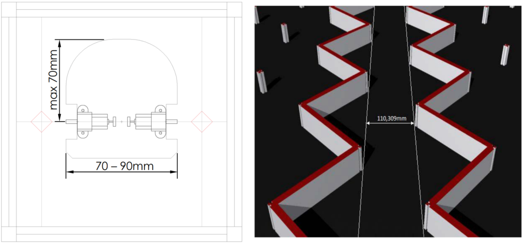
- Dimensions – Classic Class (180mm cells):
- Maximum distance between the center of curvature and the end of the robot: 70mm
- Width: between 70 and 90mm
- For performance and speed, DC motors are definitely the best choice as they are small and lightweight, but they require closed-loop control (with an encoder).
- Two wheels: offer a simpler assembly.
- Four wheels: small gaps or misalignments are crucial for the micromouse’s performance. The main advantage of this geometry is that it allows the robot to achieve much greater accelerations and decelerations compared to two-wheeled robots.
Electronic Design
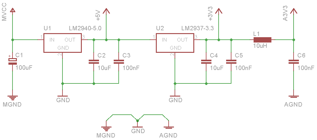
- Power Supplies – Example Circuit:
- Best practices to avoid noise issues in the robot:
- GNDs (digital, analog, and motor grounds) should be separated and connected only at a single point (usually at the battery connector).
- The analog part is the most critical in terms of noise, so the inductor L1 functions to decouple switching noise from the digital circuit and provide a ‘cleaner’ power supply to the analog circuits (distance sensors).
- Encoders:
- Linear resolution – equation:
- linear_resolution[mm] = (D * π) / (ppr * f)
- D: Wheel diameter [mm]
- ppr: Encoder resolution [ppr]
- f: Reduction factor (use 1 for an encoder installed on the wheel)
- Linear resolution – equation:

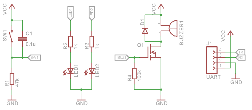
- User Interactions Features:
- Buttons
- LEDs
- Buzzer
- Bluetooth
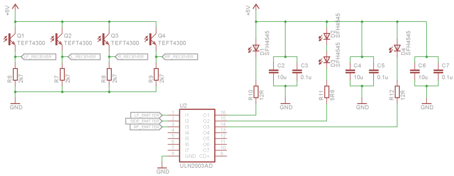
- Sensors – Example Circuit:
- Emitters:
- Attention: Permissible Pulse Handling Capability
- Full Angle: ≤10°
- Radiant Intensity: ≥300mW/sr
- Receivers:
- Attention: Wavelength (nm) matched with the emitter
- Angle Sensitivity: 30° – 60°
- Emitters:
- Sensors – Positioning:
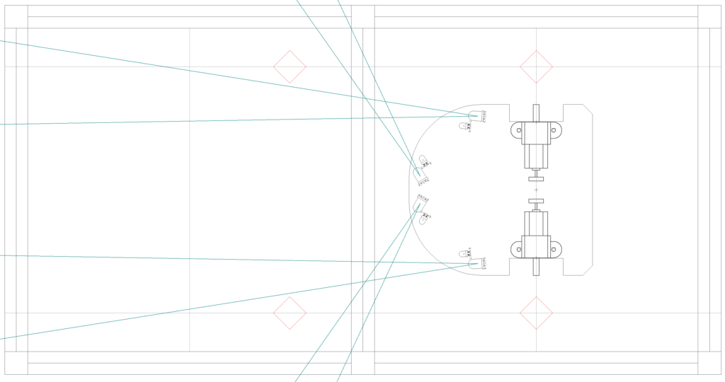
- The robot’s center of curvature must be at the center of the cell
- The side sensors are positioned so that their field of view extends slightly in front of the post
- The front sensors must reach a front wall at a distance of one and a half cells
- Extra – Sensor reading:
- Trigger the LEDs in short bursts (pulses)
- Since the LED current will be pulsed, it is possible to drive it with a much higher current, which improves the signal-to-noise ratio and reduces the influence of ambient lighting.
Controller Design
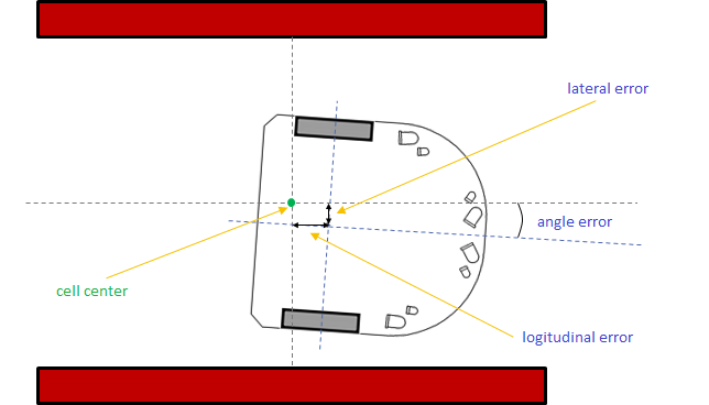
- Error Types:
- Lateral and angle errors can be corrected with the aid of side sensors, which intuitively provide information on how aligned the micromouse is within the maze, such that ideally, the readings from these two sensors should be the same.
- For correcting longitudinal errors, wall transitions (wall/no wall/post) can be used, and front sensors can be employed when there is a front wall.
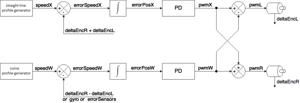
- Proportional-Derivative (PD) Controller:
- In this controller, two setpoints are adjusted: translational speed (speedX) and rotational speed (speedW).
- The manipulated variables are the duty cycles of the two motors.
- On a straight path, speedW should be zero, while on curves, speedX and speedW are constants different from zero. To perform a turn around the robot’s own axis (pivot turn), speedX should be zero.
- Speed Profiler:
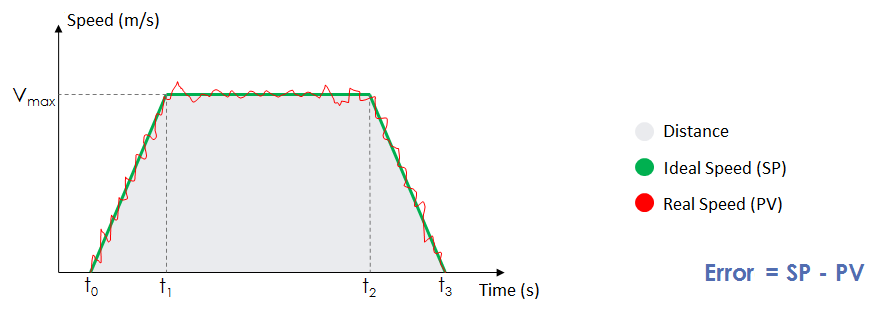
- Techniques used to generate speed setpoints.
- Produces a trapezoidal velocity profile as a function of time.
- The distance traveled by the robot is obtained from the area of the trapezoid.
- The ramps between [t0; t1] and [t2; t3] are necessary because it is not possible to accelerate or decelerate the micromouse instantaneously.
Firmware
- Below are examples of code.
- Please note that these are only for demonstrating the triggering/controller logic, and the functions should be adapted according to the microcontroller used.
Sensor Reading
C
/* This function should be called every 1ms */
void readSensors(void)
{
    /* Reading background noise from the environment */
    left_front = readADC(LF_RECEIVER);
    left_side = readADC(L_RECEIVER);
    right_side = readADC(R_RECEIVER);
    right_front = readADC(RF_RECEIVER);

    /* Current time */
    uint32_t t0 = getMicros();

    /* Front left sensor reading */
    turnOn(LF_EMITTER);
    while((getMicros() - t0) < 60);
    left_front = readADC(LF_RECEIVER) - left_front;
    turnOff(LF_EMITTER);
    if(left_front < 0) left_front = 0;
    while((getMicros() - t0) < 140);

    /* Front right sensor reading */
    turnOn(RF_EMITTER);
    while((getMicros() - t0) < 200);
    right_front = readADC(RF_RECEIVER) - right_front;
    turnOff(RF_EMITTER);
    if(right_front < 0) right_front = 0;
    while((getMicros() - t0) < 280);

    /* Reading the side sensors */
    turnOn(L_EMITTER);
    turnOn(R_EMITTER);
    while((getMicros() - t0) < 340);
    left_side = readADC(L_RECEIVER) - left_side;
    right_side = readADC(R_RECEIVER) - right_side;
    turnOff(L_EMITTER);
    turnOff(R_EMITTER);
    if(left_side < 0) left_side = 0;
    if(right_side < 0) right_side = 0;

    /* TOTAL TIME: 340us */
}
Controller
C
/* Speed controller for translational + rotational movement */
/* This function should be called every 1ms */
void controller(void)
{
    /* Calculates feedback from encoders, sensors and gyroscope */
    /* K_GYRO and K_SENSORS are constants to adjust the scales */
    feedback_encW = delta_encR - delta_encL;
    feedback_sensors = error_sensors / K_SENSORS;
    feedback_gyro = gyro / K_GYRO;

    /* Calculates the PVs (process variable) of the controller */
    pvX = delta_encR + delta_encL;
    pvW = 0;
    if(use_encoders) pvW += feedback_encW;
    if(use_sensors) pvW += feedback_sensors;
    if(use_gyro) pvW += feedback_gyro;

    /* Calculates errors (error = Setpoint - PV) */
    /* The “+=” represents the integrative operation of speed = position */
    error_posX += speedX - pvX;
    error_posW += speedW - pvW;

    /* Runs the PD (Proportional Derivative) controller */
    /* KP_X, KD_X, KP_W and KD_W are the PD controller constants */
    posPwmX = KP_X * error_posX + KD_X * (error_posX - last_error_posX);
    posPwmW = KP_W * error_posW + KD_W * (error_posW - last_error_posW);

    /* Records the previous errors for the derivative action */
    last_error_posX = error_posX;
    last_error_posW = error_posW;

    /* Calculates the PWMs of the left and right motors */
    pwmL = pwmX - pwmW;
    pwmR = pwmX + pwmW;

    /* Runs the command to update the motors' PWMs */
    setPwmL(pwmL);
    setPwmR(pwmR);
}
Example Project – Micromouse
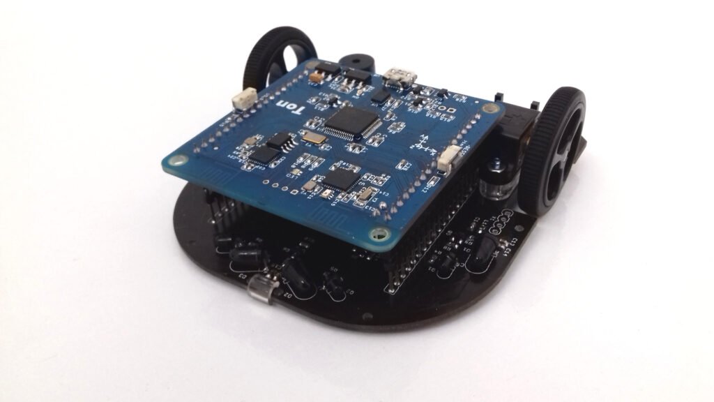
TON-BOT robot is a 3-in-1 mobile robotics kit, designed for learning how to develop maze-solving robots (micromouse) and line-following robots (robotracer). It can also be controlled wirelessly via Bluetooth.
- Features:
- Motors: Pololu micro motor with metal gearbox – 1000 rpm
- Wheels: 32x7mm (plastic and rubber)
- Encoders: Magnetic quadrature – 360 ppr
- 8 Line sensors: QRE1113GR
- 4 Wall sensors: SFH4545 (LED) / TEFT4300 (phototransistor)
- Motor H-Bridge: TB6612FNG
- Battery: LiPo 1S 600mAh
- Integrated charger + Battery monitor + Bluetooth 4.0 + Buzzer + Accelerometer/gyroscope/magnetometer + RGB LED + Wi-Fi
✳️ This is an open hardware project: GitHub
⭐ BONUS: Flood Fill code
💬 Contact me in case of questions, comments, or suggestions.